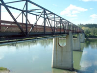
Bridge Crossings
 Urecon offers a complete range of pre-insulated pipe for the freeze protection of bridge crossings.
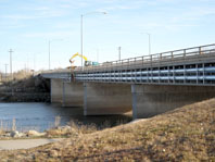
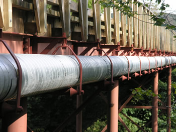
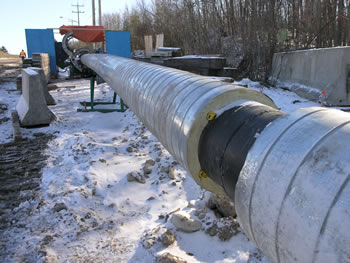
Urecon U.I.P.® pre-insulated water and sewer pipes take a longer time to freeze and are ideally suited for bridge crossing applications. There are hundreds of bridge crossings in Canada and the USA where Urecon pre-insulated pipe has been installed to prevent freezing. In most cases, bridge crossings are a minor above ground portion of a conventional municipal system. They are often located in major urban centers in southern Canada and the northern United States.
Most bridge crossing pipes are relatively short (under 60 m (200 ft)), have a constant flow and do not require electric tracing. In some cases where there are periods of no flow, or extremely cold ambient temperatures, electric heat tracing may be required. Our THERMOCABLE® heat tracing system is available to compensate for heat losses through the insulation and prevent freezing.
Advantages
There are several advantages in using U.I.P.® pre-insulated pipe for bridge crossings over other field insulation methods, including:
- Economical installed cost: pipe arrives on site insulated and ready to install.
- Excellent insulating value: polyurethane has the lowest K value of all insulations used in the construction industry today.
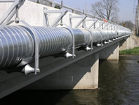
- No heat wicking: supports are outside the insulation.
- High compressive strength: permits installation on roller supports.
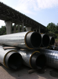
- Polyurethane insulation is extruded without seams or joints onto the pipe.
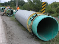
- Various outer protective jackets are available depending on the application, including:
- 1.27 mm (50 mil) thick polyethylene.
- 1.90 mm (75 mil) thick polyethylene.
- Spiwrap®, galvanized steel or aluminum lock seam outer jacket.
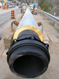
- PE seamless casing
- Light weight.
- Factory quality control of both polyurethane insulation and outer jacket.
K Values of Some Common Pipe Insulation Materials
| Insulation Material | K Value (Metric) | K Value (English) |
| Polyurethane Foam | 0.020 - 0.026 W/m°C | 0.14 to 0.17 Btu • in/ft2 • hr •°F |
| Polyisocyanurate Foam | 0.020 - 0.027 | 0.14 - 0.19 |
| Polystyrene Foam | 0.0276 | 0.20 |
| Fiberglas | 0.033 - 0.039 | 0.23 - 0.25 |
| Cellular Glass | 0.038 - 0.040 | 0.31 - 0.33 |
| Calcium Silicate | 0.059 - 0.068 | 0.41 - 0.47 |
 Choice of Core Pipe
Urecon can pre-insulate any type of core pipe. The following core pipes have been successfully used in bridge crossing applications:
- Ductile Iron, with locking joints (push-on joints are not acceptable unless restrained).
- Polyethylene, butt fused joints, Hugger® couplings or flanged.
- PVC, self-restrained or solvent weld joints (push-on joints are not acceptable unless restrained).
- Carbon or stainless steel, welded joints, Victaulic® grooved with couplings or flanged. FRP, with glued or butt and strap joints.
Design
There are several design factors that must be taken into consideration when designing a pre-insulated pipe bridge crossing.
- Heat Loss: Urecon provides a complete computer assisted engineering service to determine heat loss, time to freeze, fluid outlet temperature, tracing wattage (if required), etc., based on the specific requirements of each project.
Time to Freeze and Heat Loss For U.I.P.® Pre-Insulated Pipe
| Nominal Pipe Diameter |
Pipe Ambient -18°C (0°F) | Pipe Ambient -34°C (-30°F) | |||||
| Time to Freeze HRS. | Heat Loss | Time to Freeze HRS. | Heat Loss | ||||
| mm | in | No Insulation | 50 mm (2 in) U.I.P.® |
(watts/m) | No Insulation | 50 mm (2 in) U.I.P.® |
(watts/m) |
| 19 | 0.75 | 1 | 18 | 1.7 | 1 | 9 | 3.1 |
| 25 | 1 | 1 | 40 | 2.0 | 1 | 21 | 3.6 |
| 30 | 1.25 | 1 | 40 | 2.2 | 1 | 21 | 4.1 |
| 40 | 1.5 | 1 | 50 | 2.4 | 1 | 26 | 4.4 |
| 50 | 2 | 1 | 71 | 2.8 | 1 | 38 | 5.1 |
| 75 | 3 | 1 | 121 | 3.6 | 1 | 64 | 6.5 |
| 100 | 4 | 2 | 175 | 4.3 | 1 | 93 | 7.8 |
| 150 | 6 | 3 | 295 | 5.7 | 2 | 156 | 10.4 |
| 200 | 8 | 6 | 413 | 7.0 | 3 | 219 | 12.8 |
| 250 | 10 | 9 | 542 | 8.3 | 5 | 286 | 15.2 |
| 300 | 12 | 13 | 665 | 9.5 | 7 | 352 | 17.5 |
| 350 | 14 | 15 | 744 | 10.3 | 8 | 392 | 18.9 |
| 400 | 16 | 20 | 862 | 11.5 | 10 | 456 | 21.0 |
| 450 | 18 | 28 | 996 | 12.5 | 14 | 514 | 23.5 |
| 500 | 20 | 36 | 1180 | 13.6 | 18 | 609 | 25.6 |
Note:
- No safety factor included; results are nominal; assumes initial water temperature of 1.11°C (34°F).
- To convert watts to BTU, multiply by 3.414.
- To convert meters to feet, multiply by 3.28.
- Values are approximate and are based on schedule 40, steel pipe.
- Weight: The weight of the core pipe filled with liquid and the weight of the insulation must be summed in order to calculate the size of the bearing plates at support points.
Adequate support for any piping system is a matter of great importance. In practice, support spacing is a function of pipe size, operating temperatures, the mechanical properties of the pipe material, weight of the pipe when full of water and the compressive strength of the U.I.P.® insulation and outer jacket. See weight chart here.
To ensure satisfactory operation of a bridge crossing piping system, the location and type of hangers should be carefully considered. The principles of design for steel piping systems are generally applicable to pre-insulated bridge crossing applications, with some notable areas where special consideration should be exercised.
- Concentrated loads (i.e. valves, flanges, expansion joints, etc) should be supported directly to eliminate high stress concentrations, especially on plastic pipe systems. Should this be impractical, the pipe must then be supported immediately adjacent to the load.
- In systems where large fluctuations in temperature occur, allowance must be made for expansion and contraction of the piping system. If changes in direction are used to allow for expansion and contraction, the hangers must be placed so this movement is not restricted. There is a considerable variation in the expansion and contraction of different pipe types, as can be seen from the following table. Changes in length indicated are approximate and may vary depending on the actual resin used by a particular plastic pipe manufacturer. When calculating the expansion and contraction of a bridge crossing, consider the change in water temperature throughout the year. Remember, the pipe will be insulated from extreme ambient temperatures, assuming the pipe remains full of flowing water at all times.
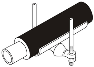
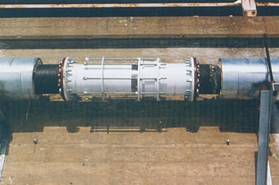 |
| Expansion joint, prior to insulating on a
pre-insulated, ductile iron pipe bridge crossing. |
Linear Expansion and Contraction of Various Pipe Cores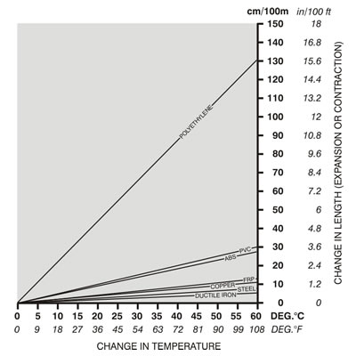
- Changes in direction (e.g. 90° elbows) should be supported as close as practical to the fitting to avoid introducing excessive torsional stresses into the system (especially on plastic pipe systems).
- Pipe joints must be fixed: push-on joints are not acceptable unless restrained.
- Support spacing must be carefully calculated, considering the type of pipe, diameter, weight, type of joints, etc. The support spacing must be calculated in conjunction with the core pipe manufacturer.
- If the pre-insulated pipe is to traverse bridge bulkheads through drilled holes, the finished outer diameter of the insulation must be verified with Urecon before the holes are drilled.
- The above are general guidelines for the design of U.I.P.® pre-insulated bridge crossings. Once the type of core pipe has been chosen, the pipe manufacturer must be contacted to verify the design for that particular type of pipe.
- Heat tracing of bridge crossings often involves consideration of above ground and shallow buried pipe on the same electrical circuit – where ambients are often different. The dual controlling feature of the UTC thermostat allows guarding against ambient temperature differential in spring and fall. See program code #11 as an example. See Heat Tracing for more information.
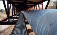
Typical Pipe Support for Pre-Insulated Pipe
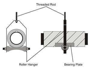
Hangers should be of the roller type so as not to restrict movement. Clamp type hangers may be used in some instances to allow expansion in a certain direction. When suspending U.I.P.® pre-insulated pipe under a bridge, the weight must be distributed over a calculated load bearing area so as not to exceed the compressive strength of the insulation. Another benefit is that a smooth bearing surface is obtained to permit longitudional expansion and contraction of the pre-insulated pipe on the roller hangers. Usually 18 ga. (minimum thickness) bearing plates 450 mm (18 in) long and 1/3 the insulation circumference are used to distribute the weight. Urecon will be pleased to advise the gauge, length and size of bearing plates required for your particular application.
Pipe Joints
See Metal Spiwrap Outer Jacket Joints – Above Ground and Welded Joints – Above Ground
Fittings
Insulation kits for flanges, couplings, fittings, expansion joints, etc., shall consist of rigid polyurethane foam with a fully bonded polymer protective coating on all exterior surfaces, including ends. Kits to be supplied complete with silicone caulking for seams, stainless steel attachment straps, clips and heat shrink sleeves to seal between pipe and kits. In the case of metal jacketed pipe, insulation kits shall have outer form fitting covers of the same material as the pipe jacket.
Some typical insulation kits used for bridge crossing applications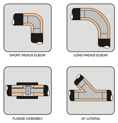
Typical Specifications
- EN-DS-03E - U.I.P. system - Spiwrap above grade
- EN-DS-02E - U.I.P. Standard System - below grade
- EN-DS-04E - U.I.P. System – PE casing above grade
- EN-DS-05E - U.I.P. System - Extruded PE above grade - Calmar Only
Related Literature